Production line configuration

Coaxial Cable Production Line

Plan centre-conductor preparation, solid or foamed dielectric extrusion, shielding interfaces and outer sheathing for the specified coaxial cable.

Explore the production route
Coaxial Cable illustration
Coaxial CableApplication illustration

Define the cable you want to produce

Centre conductor dimensions, dielectric material and structure, shielding, finished diameter and production requirements.

Centre conductor → dielectric → shield structure → outer sheath

Indicative process route; confirm against your cable drawing.

Selection priority

Dielectric design and dimensional requirements

Choose where your production begins

Centre-conductor preparation, dielectric extrusion and shielding can be purchased as separate material inputs or made in-house. The selected starting point changes equipment ownership, not the finished-cable requirements.

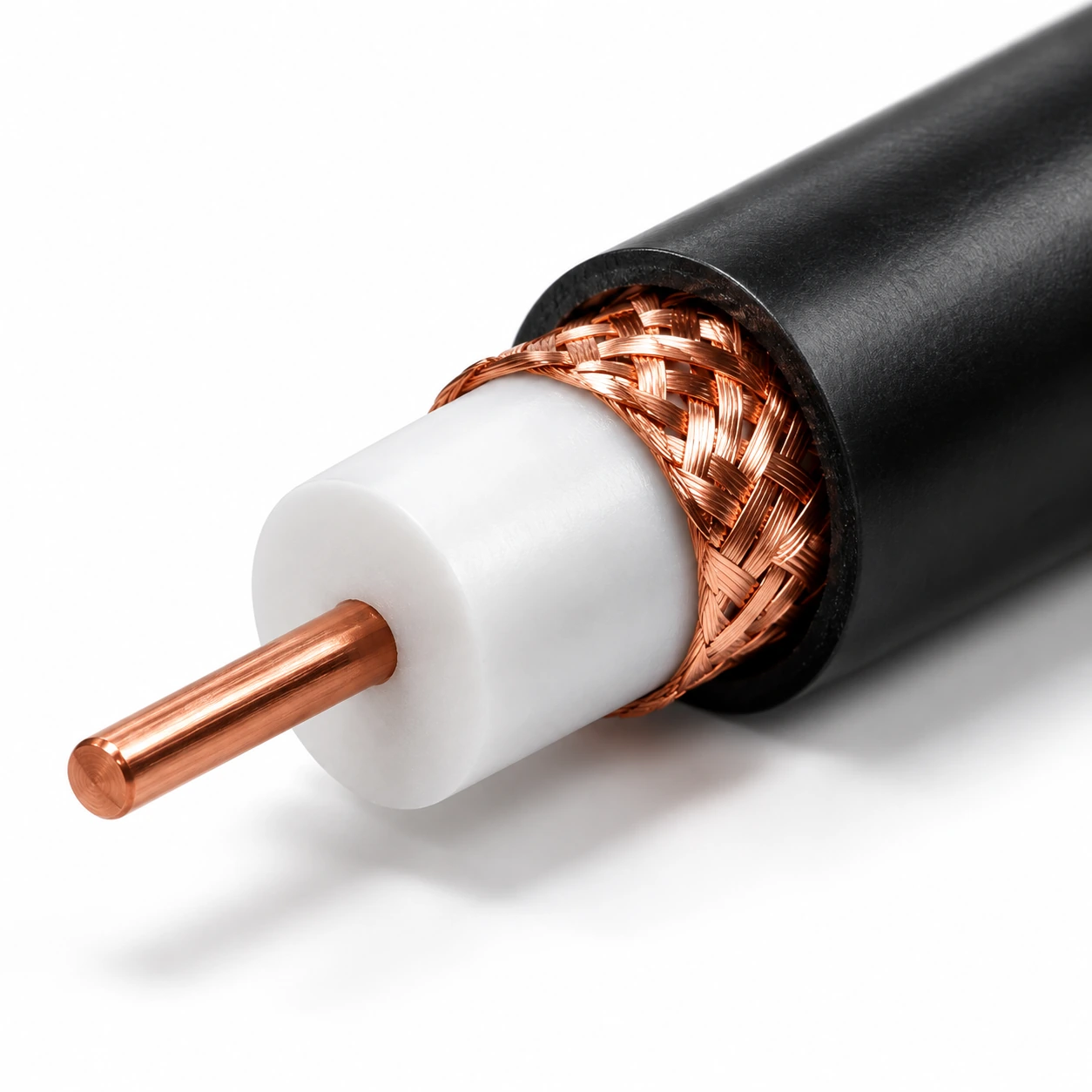
Coaxial cable cross-section — application illustration
Coaxial cable cross-section — application illustrationReview the conductor-to-dielectric interface; the selected dielectric extrusion system is not shown.
Compare the equipment boundary

Buy the specified centre conductor

  1. Dielectric
  2. Specified shields
  3. Jacket
  4. Inspect

Dielectric extrusion → specified foil or braid layers → jacket → inspection and take-up.

Supply boundary & incoming-material checks
Outside or separately confirmed
Drawing may be excluded if the conductor arrives at the required size and condition.
Check the incoming material
Conductor material, diameter, surface condition and reels; separately confirm every shielding stage.

This defines a discussion scope. The final equipment list follows the cable drawing and technical review.

Explore the production route

Select a stage to see its role, equipment and the interface to confirm.

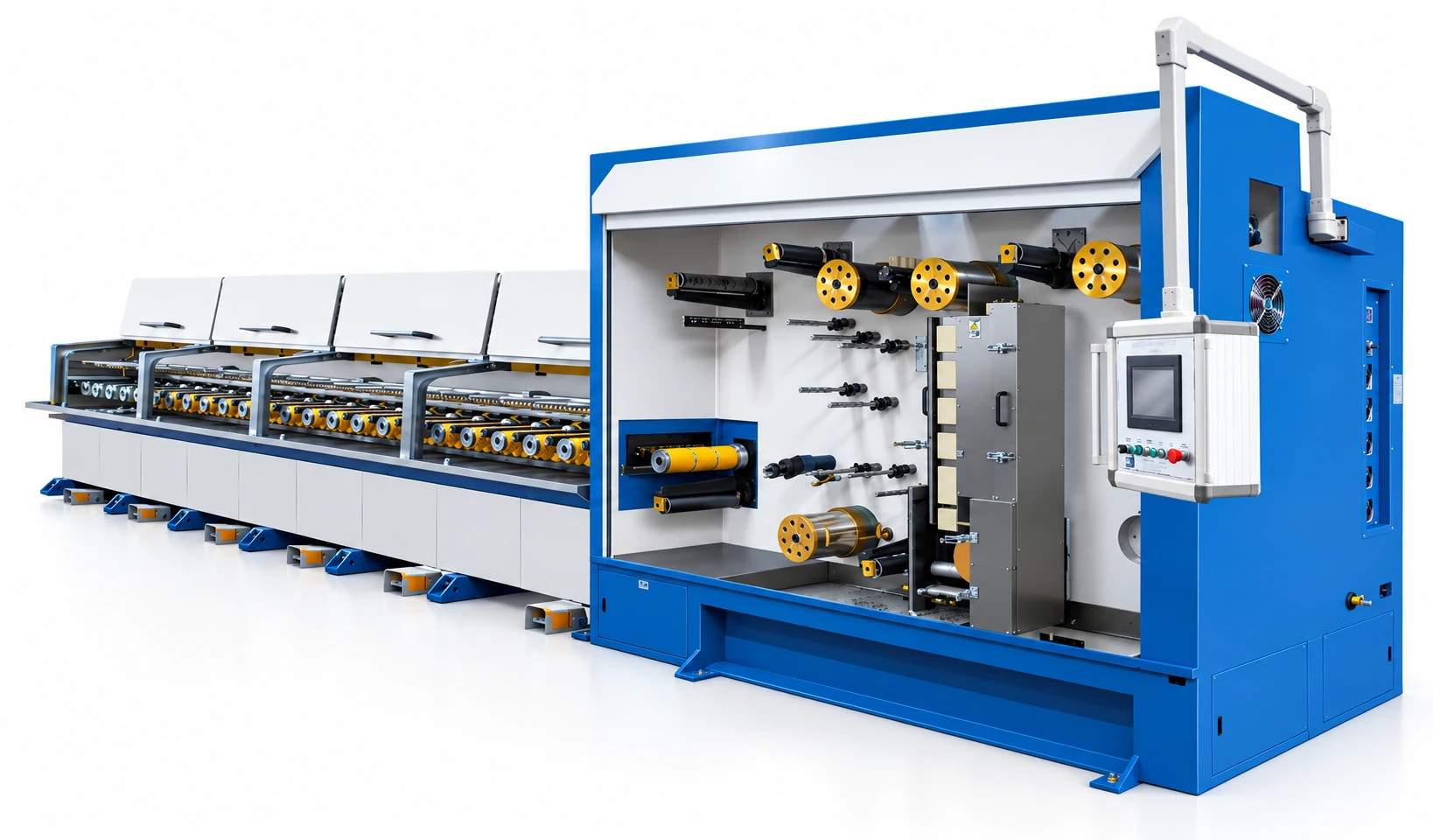
Multi-wire drawing with online annealing
Coaxial Cable

Conductor preparation

Prepare the conductor dimensions and condition needed by the next operation.

Input
Specified rod or incoming wire
Output
Centre conductor at the specified diameter

Confirm the interfaceMaterial compatibility, incoming and finished diameter, annealing needs and supply reels.

Review wire drawing & annealing equipment
Stage 1 of 5

Compare the construction choices

A different cable structure can change machines, tooling and supply responsibilities. Compare these choices before agreeing the equipment list.

Coaxial cable cross-section — application illustration
Coaxial cable cross-section — application illustrationReview conductor and dielectric dimensions; this is not evidence of a selected solid-dielectric line.

Solid dielectric

Review extrusion around the specified centre conductor with the required dimensional controls.

What changes

Selecting solid insulation does not remove the need to validate the full cable construction and electrical requirements.

Confirm before selection

Provide the dielectric compound, conductor and dielectric diameters and dimensional tolerances.
Explore the equipment for this cable

Open an equipment family to compare machine types and reference specifications.

Agree the output, site and acceptance basis

A connected line needs a common specification at every handover. Use these points to test whether the proposed scope is complete.

Production target

Capacity across extrusion and shields

Compare the dielectric, shielding and jacket stages on the same finished-cable target.

Review the planning details

If a shield stage operates off-line or through another supplier, include its output, transfer reels and intermediate stock in the plan.

Factory interfaces

Protect intermediate geometry

Coordinate reel sizes, winding and handling between dielectric, shielding and sheathing.

Review the planning details

Obtain the material and product handling requirements before defining tension, reel movement and storage arrangements.

Acceptance plan

Trial and acceptance

Agree conductor and dielectric dimensions, the shield construction and jacket requirements with the required finished-cable electrical tests.

Review the planning details

Process inspection and an equipment demonstration cannot alone establish the final cable performance.

Put responsibilities in writing

Identify who provides trial materials, utilities, reels, testing and any external process. Agree how results will be recorded and what must be resolved before acceptance.

Compare investment on the same scope

A useful budget separates the machines from plant preparation, external processing and start-up requirements. No standard package price can replace a defined cable specification.

Configuration and purchasing choices that change the budget
DecisionWhat enters the scopeHow to compare
Dielectric processSolid or foaming configuration, material preparation, head and downstream controls.Keep conductor, compound, dielectric structure and dimensional targets consistent across offers.
Shield package and validationFoil or taping devices, separate braiding, intermediate reels and the agreed finished-cable test scope.Identify the supplier and acceptance responsibility for each shield layer.
Phased purchaseA purchased dielectric or shielded core can allow a later-stage manufacturing scope.Confirm incoming test evidence, handling limits and interfaces before excluding upstream equipment.
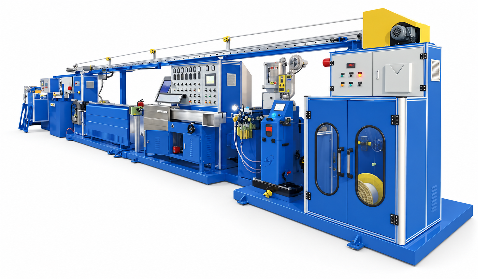
Catalogue extrusion equipment example

Use the catalogue as a starting point

The catalogue covers extrusion equipment and physical and chemical foaming applications. These provide process options to discuss for the specified dielectric.

This photograph is an extrusion example, not proof of a selected coaxial configuration. Confirm the foaming system, shield supply and finished-cable validation separately.

Prepare your line-planning requirements

Dielectric structure

Material and solid or foamed construction guide extrusion selection.

Dimensional targets

Provide the conductor, dielectric and finished cable dimensions.

Shield construction

Identify foil, braid and any additional layers in the cable drawing.

Product validation

Agree the process requirements alongside the finished cable test plan.

Application questions

Can foamed dielectric extrusion be considered?

Yes. Physical and chemical foaming extrusion lines appear in the catalog. The correct configuration depends on the specified dielectric and cable design.

Does a line configuration guarantee electrical performance?

Finished cable performance depends on the full design, materials, process and validation. Equipment configuration should be reviewed against those requirements.

Is shielding equipment automatically included?

No. Each shielding stage and its supply responsibility should be stated in the agreed project scope.

Can a conventional extrusion line be converted to foamed dielectric production?

That requires a review of the machine, material, selected foaming process and supporting equipment. Do not assume a conventional line can be converted through settings alone. Share the existing screw, head, controls and downstream configuration.

Can we omit shielding machines if we buy shielded cores?

A jacketing-focused scope can be reviewed, provided the incoming shielded core meets the agreed construction and validation requirements. Match the reel, dimensions and handling requirements to the jacket line and define who is responsible for incoming defects.

Your Project Brief

Share the cable you want to make and the scope of your project.

Sample site: prepare and download a project brief locally. No inquiry is sent.